Objective
This experiment focuses on optimizing the performance of a fourth-order Passive All-Pass Transmittance Operator (PATO) system. The system includes components such as a load-side encoder, load-side rotating mass, spring, motor-side rotating mass, and motor-side encoder. The aim is to control the non-co-located mass with precision along a predefined bidirectional trajectory, simulating real-time control scenarios.
Accurate positioning of the non-co-located mass is critical, while maintaining minimal tracking errors and minimizing the total time for the motion. The co-located mass, at the motor side, directly benefits from torque application and angular displacement measurement via the encoder.
The experiment imposes key constraints to ensure robust performance. The scanning stroke must span 120 radians, covering at least 19.1 revolutions in both forward and backward directions. The total stroke is limited to 125 radians, leaving only 2.5 radians for turn-around motion at each end. To address production variations and uncertainties, the feedback loop’s modulus margin is capped at 6 dB. Additionally, the control system operates at a sampling rate of no more than 4 kHz.
This setup seeks to emulate practical applications, ensuring the system performs reliably under stringent requirements while achieving high precision and efficiency.
System Identification
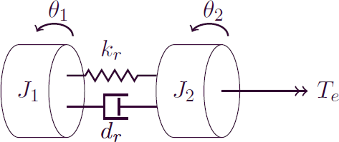
The transfer functions for the co-located and non-co-located masses are as follows:
Co-located Mass
Equation:
Equation:
Θ1 / Te = (J2 s2 + drs + kr) / (J1 J2 s4 + (J1 + J2) drs s3 + (J1 + J2) krs2)
Non-Co-Located Mass
Equation:
Equation:
Θ2 / Te = (drs + kr) / (J1 J2 s4 + (J1 + J2) drs s3 + (J1 + J2) krs2)
Given the marginal stability of the open-loop system for both co-located and non-co-located masses, the system’s frequency response function (FRF) can be measured using the Direct Method to obtain the magnitude and phase spectrum. If the system was not open-loop stable, the Indirect Method would be required to measure the FRF.
A white noise signal is used to eliminate the correlation between noise and input by sufficient averaging, leading to a more accurate estimation of the system’s transfer function. The plant’s transfer function is expressed as:
H(f) ≈ S_yu(f) / S_uu(f)
Coherence
During testing, it was observed that the motor and load encoders rotated in opposite directions. This caused the phase to start at 0° instead of the expected ±180°, shifting the Nyquist plot to the first quadrant. Multiplying the load measurements by -1 corrected this issue, relocating the Nyquist plot to the third quadrant.
From the frequency response function (FRF) measurements, the magnitude and phase spectra revealed a resonance peak at 57.4 Hz for both co-located and non-co-located masses. The resonance at 1 kHz, linked to motor dynamics, was deemed irrelevant to the primary objective.
Coherence levels between 10 Hz and the resonance frequency of 57.4 Hz improved significantly, providing better insights into the system’s dynamics. Beyond 57.4 Hz, coherence rapidly declined.
The frame size significantly affects coherence levels and resolution. Using a sampling rate of 4 kHz over 75 seconds (300,000 samples), the best coherence was achieved with a frame size of 12,000 samples, a variance of 0.3, and an overlap of 6,000 samples, resulting in 49 averaged frames. Adjusting the frame size impacted resolution and averaging. Smaller frame sizes reduced resolution, while larger sizes improved resolution but limited disturbance reduction. Optimizing frame size balanced resolution and averaging, improving data reliability and clarity in the frequency domain.
Feedback Controller
A feedback controller with a high bandwidth was designed to achieve a consistent -2 slope before and -4 slope after the resonance, ensuring stable dynamics and accurate reference tracking. A lead-lag block introduced positive phase and low-frequency gain, extending the bandwidth to 14.5 Hz. A low-pass filter above 100 Hz attenuated noise, and a notch filter at 57.6 Hz suppressed resonance effects. These measures reduced the error range to 0.17–40 mrad.
Need for Feedforward Controller
A feedforward model was introduced with a third-order motion profile, incorporating reference position, velocity, acceleration, and jerk to ensure smooth transitions between acceleration phases. A low-bandwidth controller tuned the feedforward parameters with a bandwidth of 2.61 Hz, a modulus margin of 5.7 dB, a gain margin of 7.9 dB, and a phase margin of 42.8°. Iterative adjustments to parameters reduced errors and improved reference tracking.
Experimental Results
Initially, the system exhibited an RMS error of 7.4 mrad, with a peak error of 18.28 mrad during constant velocity. An inverse notch filter was added to reduce sensitivity at the mass rotation frequency, resulting in an updated RMS error of 2.3764 mrad and a peak error of 6.2832 mrad.
Conclusion
The controller designed for the PATO setup achieved minimal error and optimal performance. The dynamics were simplified using a feedforward controller, while a high-bandwidth feedback controller with notch filters further improved tracking performance. Error analysis identified recurring errors, which were mitigated by the notch filter, ensuring robust system stability and precision.